
Intraoperative neuromonitoring (IONM) is a powerful adjunct to improve the safety of high-risk neurosurgical procedures. We present an interactive training module to help make concepts and techniques more broadly accessible to all practitioners.
We envision constant refinement of our strategies, which will be shared through this online platform, and welcome any feedback for continued improvement.
Created in fulfillment of the Master of Fine Arts in Medical Illustration at Rochester Institute of Technology. Any visual material contained in this website may not be manipulated, reproduced, extracted, or distributed without permission.
All Illustrations and models ©Xian Marie Boles and ©Wenya Linda Bi. All rights Reserved.
Content developed in collaboration with Mitali Bose, CNIM, and Matthew Toczylowski, CNIM.
Clinical content reflects the practice of the user. No clinical liability will be held for individual application of these practices.
![]()
Made possible by The Vesalius Trust for Visual Communication in the Health Sciences
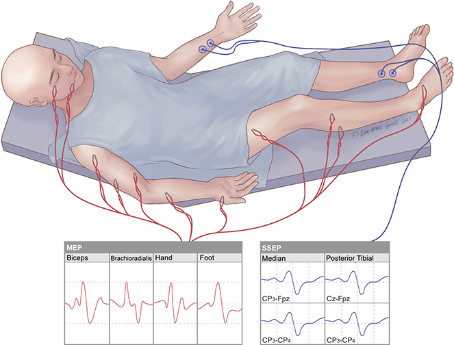
Motor Evoked Potential (MEP)
Monitors motor function by recording from electrodes placed in the muscles with stimulation delivered transcranially via electrodes under the scalp (tcMEPs) or directly to cortex via electrodes on the surface of the brain (dcMEPs)
Somatosensory Evoked Potential (SSEP)
Detects sensory responses by stimulating sensory nerves in the periphery and recording from electrodes under the scalp that generate a near-field potential to the cortex
Visual Evoked Potential (VEP)
Measures the functional integrity of visual pathways from the retina to the visual cortex of brain by recording electrical potentials from scalp overlying visual cortex in response to visual stimulus delivered to the eyes
Brainstem Auditory Evoked Response (BAER)
Measures the neural response of the auditory system, from peripheral to central, to sound (click) stimulation
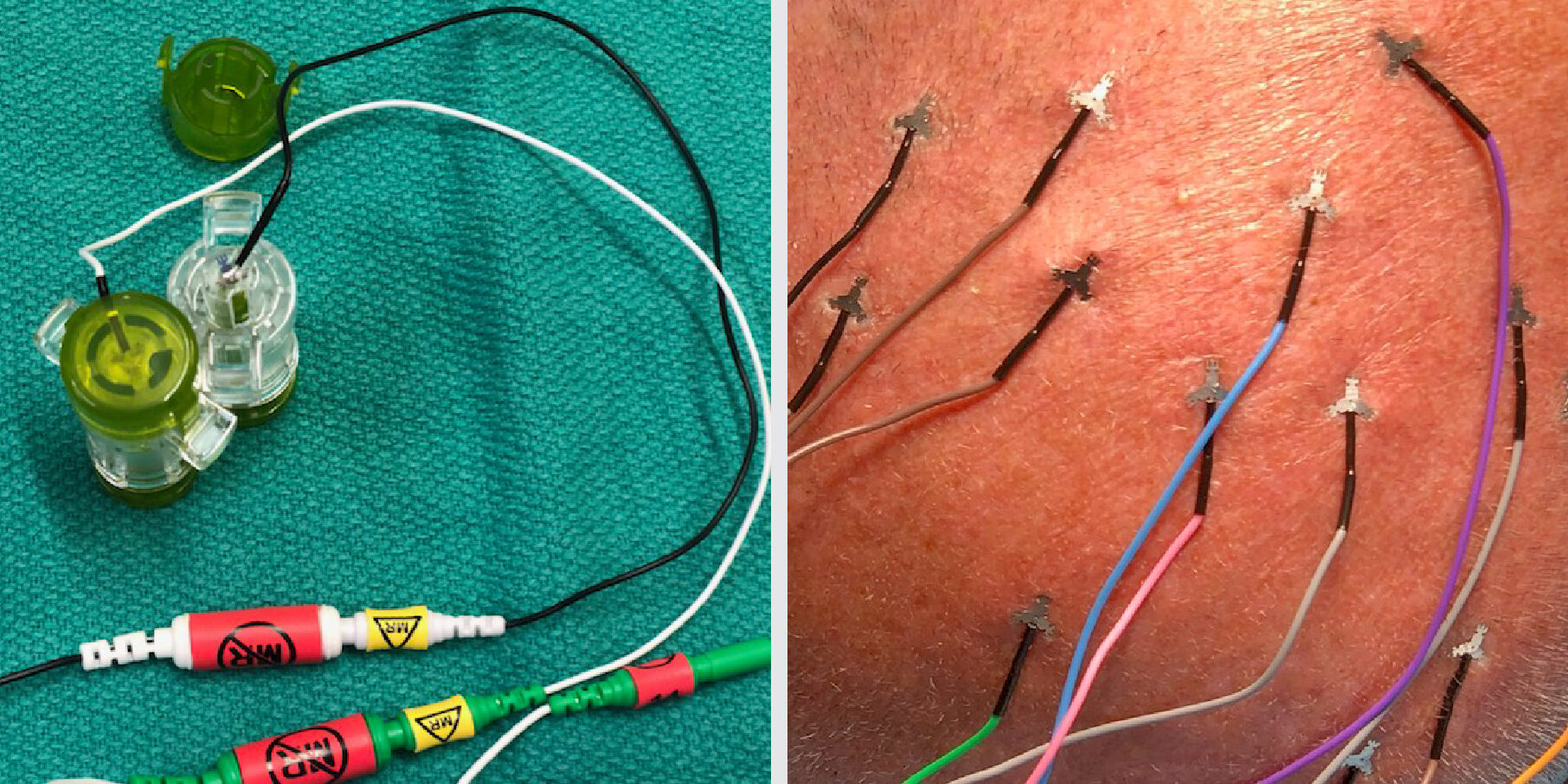
SSEP surface sticker electrode

MRI safe scalp electrodes
Basic solid paired electrodes
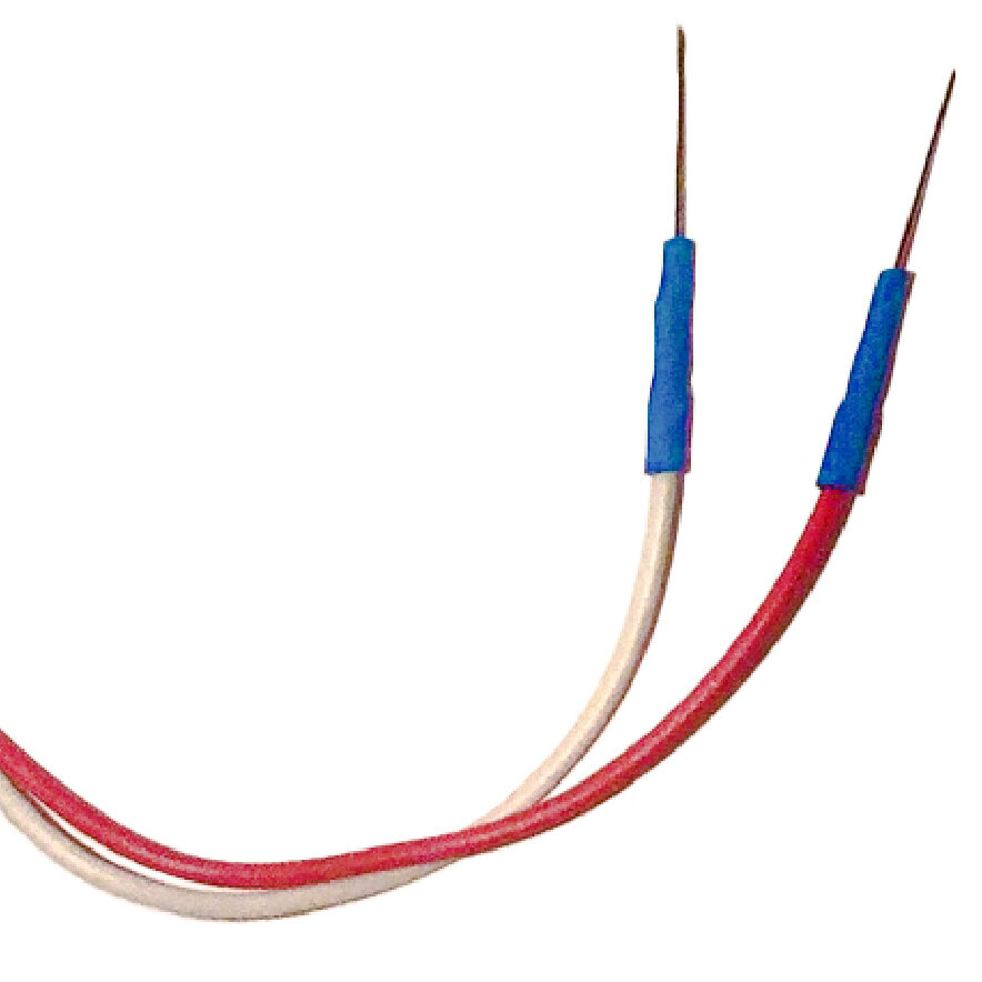
Can be interchangeable with insulated paired electrodes if corticobulbar MEP readings are desired.
Insulated paired electrodes (corticobulbar)

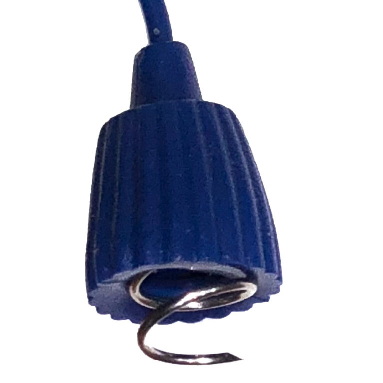
Corkscrew electrodes
Bite blocks
- 2 bite blocks are necessary when monitoring MEPs to prevent injury to the tongue
Electrode placement
- Point sharp tips away from incision and surgical field
- Place ground electrodes sufficiently far from each other to avoid stimulus artifact (e.g. for CN III and VI or for CN V and VII)
- Avoid placing electrodes on titanium hardware, shunts, or other hardware
The 10-20 system is a standardized method of head electrode placement based on the relationship between the electrode location and the cerebral cortex.
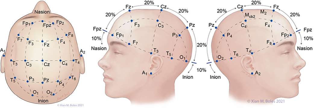
A: auricular C: central F: frontal Fp: frontal polar O: occipital P: parietal T: temporal Z: midline
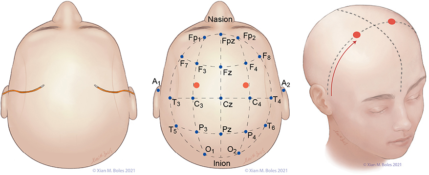
Electrodes for the Standard Bipolar setup for MEP stimulation are placed along the preauricular line, overlying the primary motor cortex (or as closely approximated as permissible by the incision).
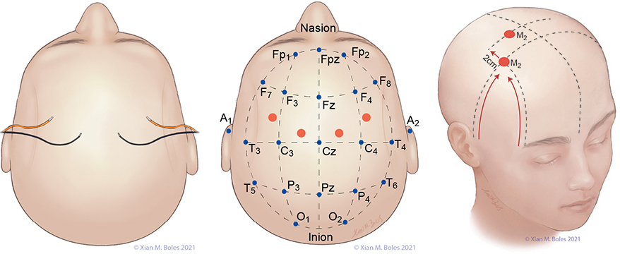
Linked quadripolar stimulation utilizes 4 scalp electrodes; stimulating from two anode electrodes placed on one hemisphere of the head to two cathode electrodes placed on the opposite hemisphere. The lateral electrodes for the linked quadripolar setup are placed on the preauricular line and intersects with a line drawn posteriorly from the junction of the superior orbital rim and the lateral orbital rim. The medial stimulating electrodes are placed approximately 1-2 cm posterior from the preauricular line, adjacent to the midline.

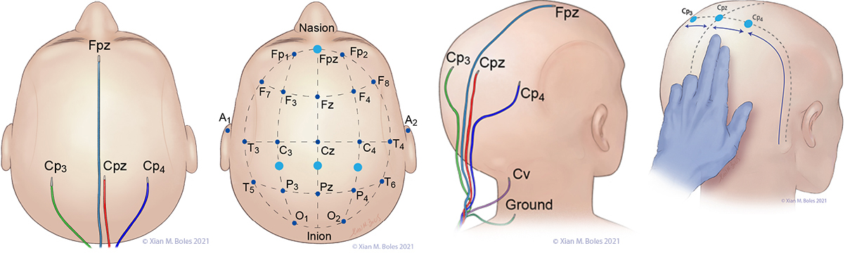
Electrodes for monitoring SSEPs are placed at Fpz, Cp3, Cpz, Cp4, and Cv. The ground electrode is placed at the base of the neck.
A short-hand approximation for the primary sensory cortex is a coronal line at the level of the mastoid process, along which Cp3, Cpz, and Cp4 can be placed.
Cp3 and Cp4 are placed approximately 3-4 cm lateral (two-finger breadths) to the midline.
Cv/Cv5 (subcortical/cervical recording electrode) is placed at the external occipital protuberance (Cv) or above the C5 vertebra on the posterior neck (Cv5).
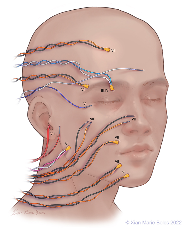
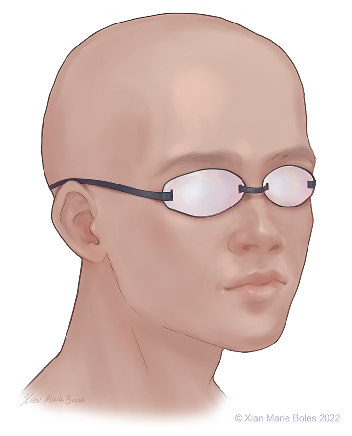
Optic (II): VEP goggles*
Oculomotor (III): Superior rectus m.
Trochlear (IV): Superior oblique m.
Trigeminal (V1): Supraorbital n.*
(V2): Infraorbital n.*
(V3): Masseter m.
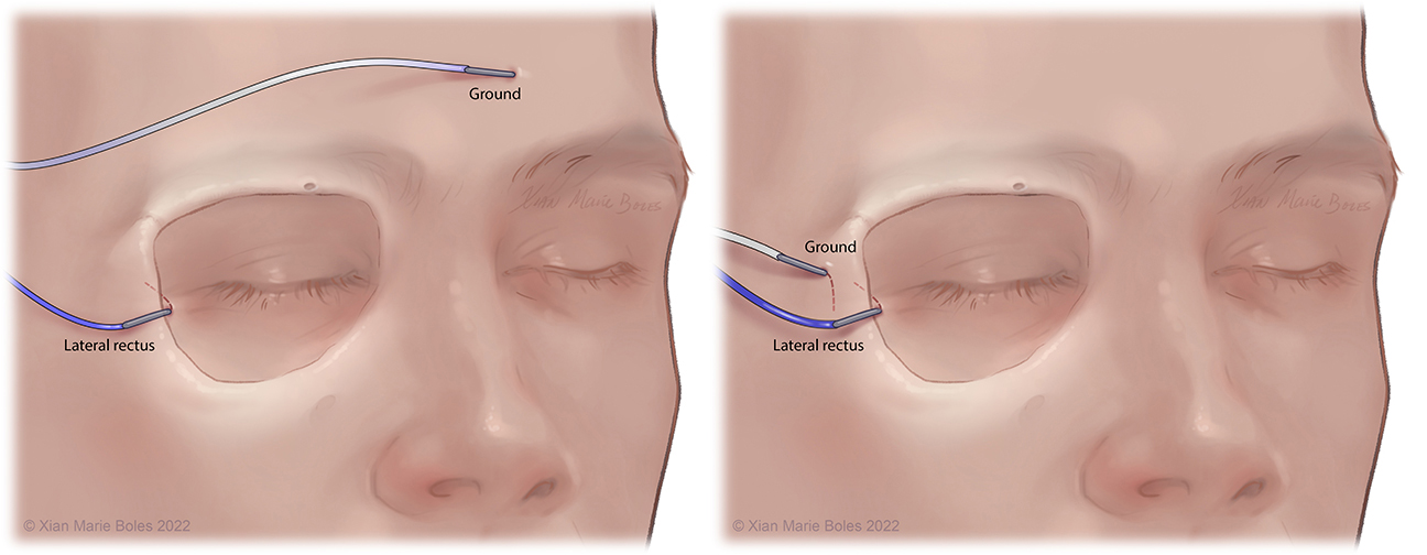
Abducens (VI): Lateral rectus m.
Facial (VII): Frontalis m.
Oculi m.
Oris m.
Nasalis m.
Buccal
Mentalis m.
Platysma m.*
Vestibulocochlear (VIII): Audio stimulator
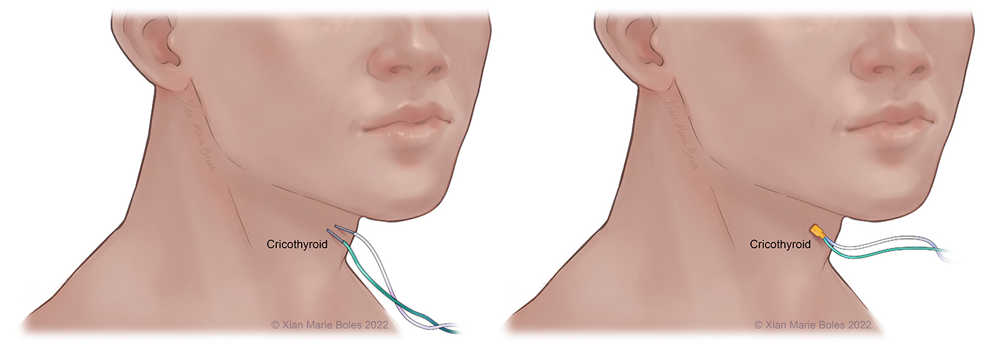
Vagus (X): Vocal cords, cricothyroid m.*
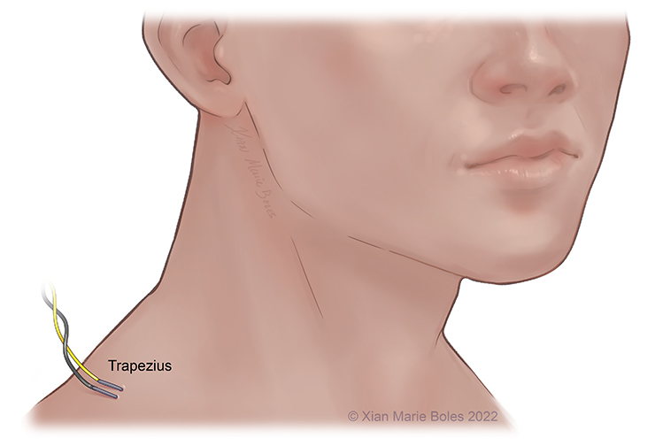
Accessory (XI): Trapezius m.*
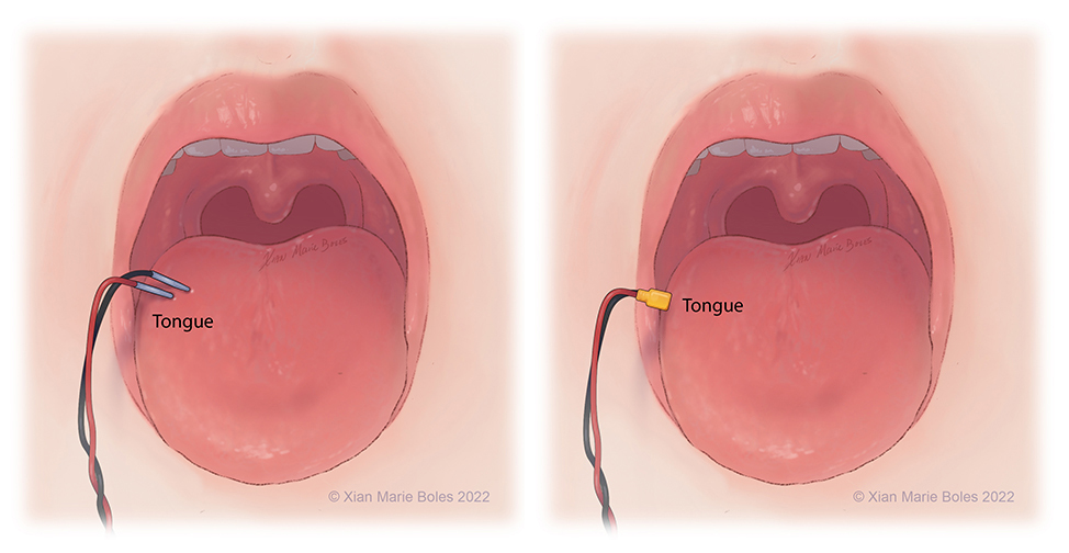
Hypoglossal (XII): Tongue*
Legend: *not pictured; m., muscle; n., nerve
VEP goggles
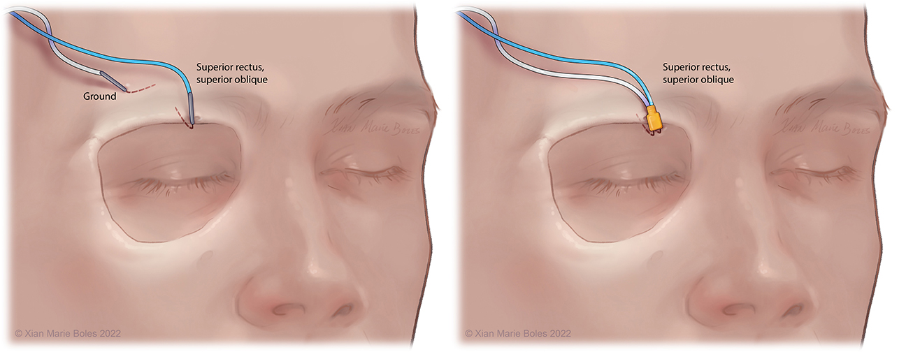
Superior rectus muscle and superior oblique muscle
Intramuscular needle is bent just past 90 degrees and slips underneath the mid-aspect of the superior orbital rim. Insulated electrodes may also be used if corticobulbar MEPs desired.
Lateral rectus muscle
Intramuscular needle is bent just past 90 degrees and slides within inside of the lateral orbital rim to rest in the lateral rectus muscle. Insulated electrodes may also be used if corticobulbar MEPs desired.
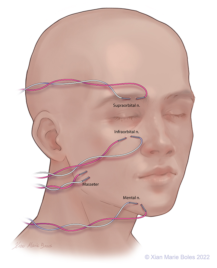
V1: Ophthalmic: Supraorbital nerve, Intramuscular needles placed around supraorbital foramen
V2: Maxillary: Infraorbital nerve, Intramuscular needles placed around infraorbital foramen
V3: Mandibular: Mental nerve and masseter muscle, Intramuscular needles placed around mental foramen (sensory branch) and in masseter muscle (motor branch)
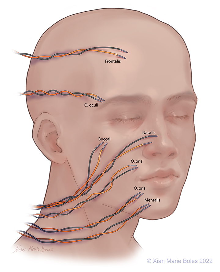
Intramuscular needles can be placed in:
Frontalis muscle
Orbicularis Oculi muscle
(Upper and lower lids may be monitored separately)
Buccal muscle
Nasalis muscle
Orbicularis Oris muscle
(Upper lip and lower lip may be monitored separately)
Mentalis muscle
Platysma
(not pictured)
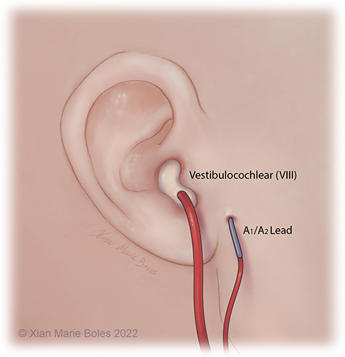
Brainstem Auditory Evoked Response (BAER)
The BAER/ABR measures the neural response of the auditory system to sound stimulation.
It is a test of auditory brainstem function in response to auditory (click) stimuli.
The BAER audio stimulator is placed inside ear, reinforced with bone wax on top to hold in place.
The ground electrode is placed in close proximity, away from the surgical incision.
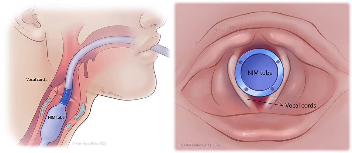
Vocal cords
NIM (Neural Integrity Monitor) tube
Cricothyroid muscle
Additional coverage of CN X may be provided by insertion of insulated or regular needles into the cricothyroid muscle.
The Laryngeal Adductor Reflex (LAR) may be measured with paired electrodes on the vocal cord (such as with the NIM tube) and monitors the afferent and efferent pathway involved in the vagus nerve function.
Trapezius muscle
Intramuscular needles
Tongue
Bilateral pairs of intramuscular needles
MEPS
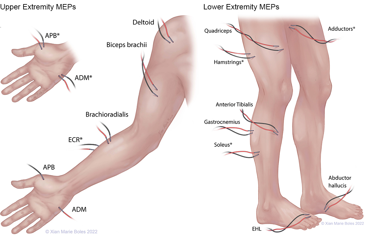
APB: Abductor pollicis brevis ADM: Abductor digiti minimi ECR: Extensor carpi radialis EHL: Extensor hallucis longus
*high-density coverage
SSEPS
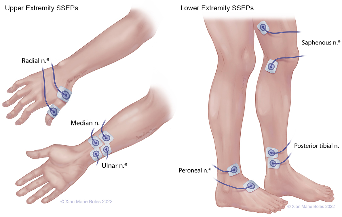
*high-density coverage
American Electroencephalographic Society guidelines for standard electrode position nomenclature. J Clin Neurophysiol 1991;8:200-2.
Deletis V, Fernandez-Conejero I. Intraoperative monitoring and mapping of the functional integrity of the brainstem. J Clin Neurol 2016; 12(3):262-273.
Dong CCJ, MacDonald DB, Akagami R, Westerberg B, AlKhani A, Kanaan I, Hassounah M. Intraoperative facial motor evoked potential monitoring with transcranial electrical stimulation during skull base surgery. Clinical Neurophysiology 2005; 116:588-596.
Chen JH, Gonzalez AA, Shilian P, Cheongsiatmoy J. An alternative transcranial motor evoked potential montage to minimize ipsilateral “crossover” motor responses. Neurodiagn J 2018; 58:218-25.
Holdefer RN, Sadleir R, Russell MJ. Predicted current densities in the brain during transcranial electrical stimulation. Clinical Neurophysiology 2006; 117:1388-97.
Raabe A, Beck J, Schucht P, Seidel K. Continuous dynamic mapping of the corticospinal tract during surgery of motor eloquent brain tumors: evaluation of a new method. J Neurosurg 2014; 120:1015-1024.
Rossi M, Sciortino T, Conti Nibali M, Gay L, Vigano L, Puglisi G, Leonetti A, Howells H, Fornia L, Cerri G, Riva M, Bello L. Clinical pearls and methods for intraoperative motor mapping. Neurosurgery 2021; 88(3):457-467.
Sinclair CF, Tellez M, Ulkatan S. Noninvasive, tube-based, continuous vagal nerve monitoring using the laryngeal adductor reflex: feasibility study of 134 nerves at risk. Head & Neck 2018; 40(11):2498-2506